Firmware source: handwired/jstrebeck/js80 and handwired/jstrebeck/jsergo
I built two mechanical keyboards from scratch. Not from a kit, and not from a PCB someone else designed. Each one started as a layout drawing, became a 3D model, came off the printer in pieces, and was wired switch by switch before getting its own QMK firmware definition. The JS80 is a compact 80 percent board. The JSErgo takes the same key count and splits it into two angled halves for a more natural wrist position.
Design Workflow
Both boards followed the same path.
- Layout in Keyboard Layout Editor . This is where the key sizes, spacing, and the split angle on the JSErgo were worked out. The exported layout also becomes the coordinates in the QMK definition later.
- Case modeling in Fusion 360. I modeled the plate and case as one body with a cutout for every switch, plus the pocket for the microcontroller and the USB-C opening. The JS80 render below is straight out of Fusion.
- 3D printing in sections. Neither case fits on my printer bed in one piece, so each was split into parts and joined after printing. The JSErgo photo shows the finished case with its off-white body.
- Hand wiring. There is no PCB. Each switch has a diode soldered to one leg, the diodes form the rows, and bare wire runs the columns. Every row and column then gets a lead to the controller. The RP2040 makes this easier because it has enough GPIO for a full matrix without any multiplexing.
- Firmware in QMK, described below.
JS80
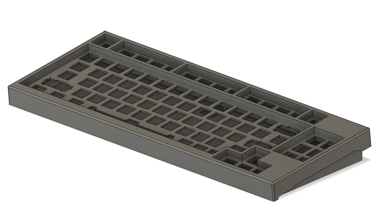
The JS80 is a standard row stagger board with a function row, a full alpha block, arrows, and a small navigation column on the right. The matrix is seven rows by seventeen columns, with column to row diodes. The keymap has a base layer plus a second layer that is mostly transparent, with the volume keys remapped, which leaves room to add a function layer later without rewiring anything.
JSErgo
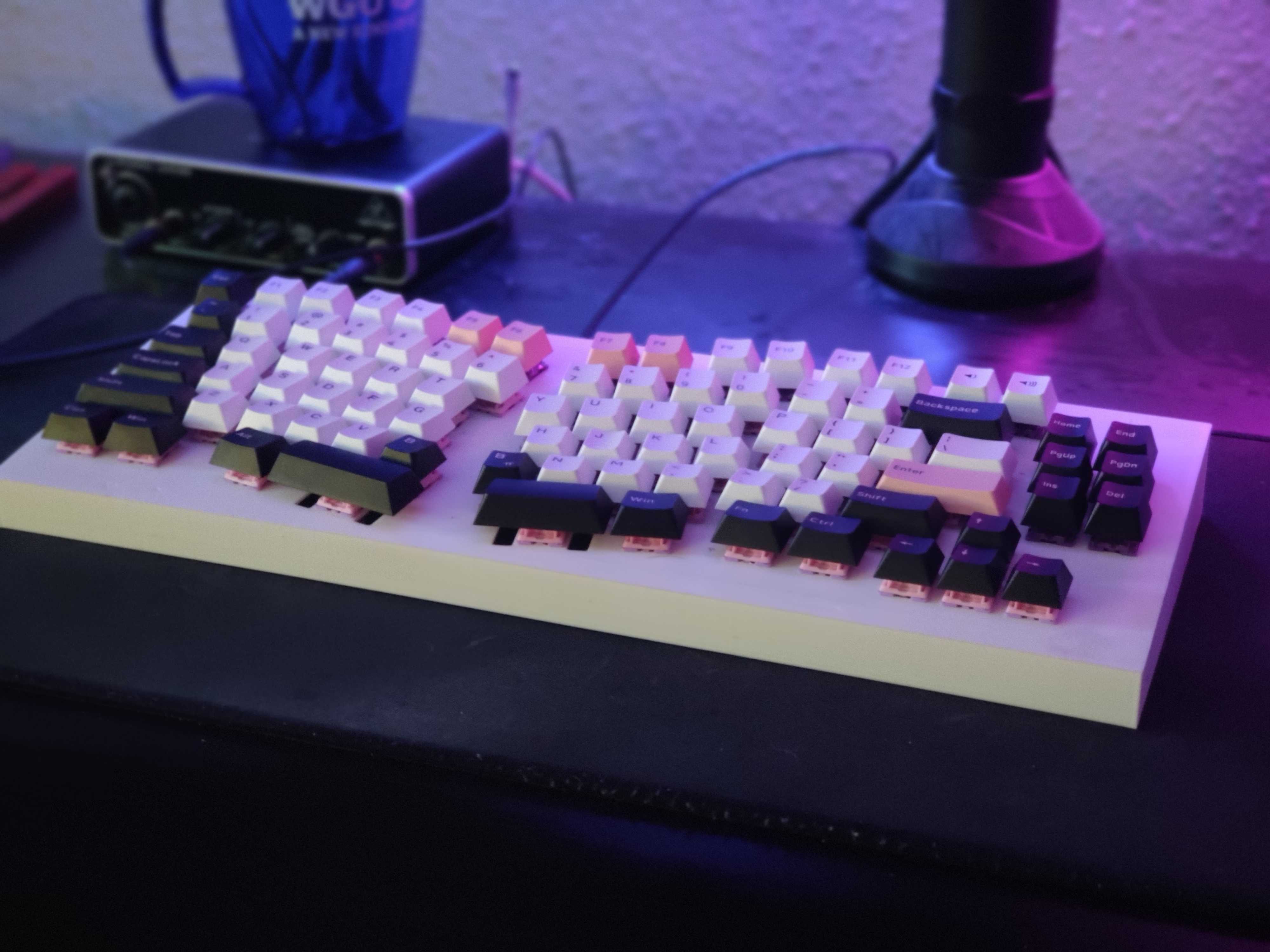
The JSErgo keeps almost the same key set but splits the alpha block into two halves angled outward, in the style of an Alice layout. The function row and the navigation cluster stay in place along the outer edges. Splitting the board this way means the matrix does not map cleanly to the physical rows, so the QMK layout lists the left edge keys first, then the left half, then the right half, each with its own x and y offsets to match the angled positions. The matrix is six rows by sixteen columns on the same controller.
QMK Firmware
Both boards run on a Keebio Elite-Pi, which is a Pro Micro footprint board with an RP2040 and USB-C. QMK’s data driven configuration means each keyboard is defined almost entirely in info.json: the processor, the bootloader, the matrix pins, the diode direction, and the physical position and width of every key. The keymap lives in keymap.json as a flat list of keycodes per layer. There is no C code beyond a stub header.
Building and flashing is two commands.
qmk compile -kb handwired/jstrebeck/js80 -km default
qmk flash -c -kb handwired/jstrebeck/js80 -km default
Bootmagic is enabled, so holding the top left key while plugging in the board drops it into the bootloader for reflashing. N-key rollover, media keys, and mouse keys are on as well.
What I Took Away
Hand wiring a board with more than eighty switches is slow and unforgiving. One cold joint means one dead key and a lot of time with a multimeter. But the payoff is a keyboard where every part, from the case geometry to the keycode on each switch, is something I chose and can change. The JSErgo in particular has become my daily driver, and the whole design is reproducible from a layout file, a Fusion model, and a firmware directory.